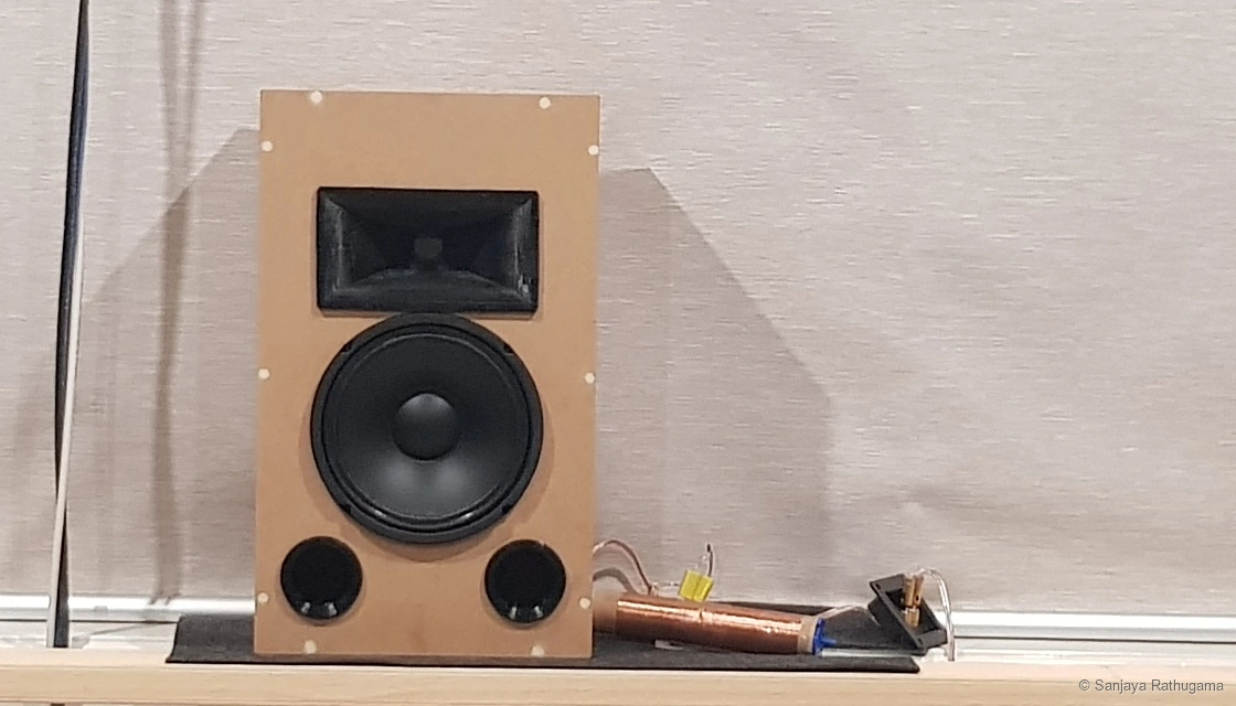
I wanted the front of the room to sound like a cinema, with dialogue and effects belonging to the picture. Designing the speakers myself was an appealing way to get there. I could choose the drivers, shape the cabinets around the space and put the effort into the parts that mattered to me.
There was, however, a fairly important gap in that plan. I had never designed a speaker around a compression driver and horn before.
I had years of electronics projects behind me, and I was comfortable designing parts and making them. Acoustics brought a different set of interactions. A horn could fit beautifully in CAD and still behave differently from what I expected. Two capable drivers could each look promising and still need considerable work to sound right together.
Three large cabinets would have been quite a commitment while I was still working those things out. So I started with one smaller speaker.
The 8-inch prototype became a place to turn the theory into something I could assemble, measure, listen to and change. It eventually led to the 12-inch LCR speakers for the shallow home-theatre front wall, but it had a useful job of its own: make the unfamiliar parts of that project understandable before scaling up.
Give the experiment a useful size
My software engineering background made the development approach familiar. Start with the uncertain part, build something that can answer a useful question, then let the feedback shape the next version. In this case, the feedback came from physical clearances, printed parts, electrical networks and sound in a room.
An 8-inch woofer kept the enclosure manageable while leaving room for a compression driver and a horn of my own design. One cabinet also meant that a change to the layout or crossover remained one experiment. I could learn from it before repeating the decision three times.
I wanted the prototype to answer a few practical questions.
| Question | What the prototype let me investigate |
|---|---|
| Could a horn and its driver fit a shallow cabinet? | Develop the acoustic passage and mounting alongside the enclosure, then check the physical combination. |
| Would the two drivers work together? | Measure each section and develop the crossover around its actual response. |
| What would a smaller enclosure give up? | Compare bass tuning, usable air volume, port dimensions and cone movement in WinISD. |
| Which decisions were worth carrying forward? | Use a working speaker to clarify the requirements for the larger front stage. |
That kept the project focused. A polished cabinet finish was less urgent than finding out whether I understood the driver integration. The geometry and mounting still needed care, because a loose or poorly aligned assembly would make the experiment harder to interpret.
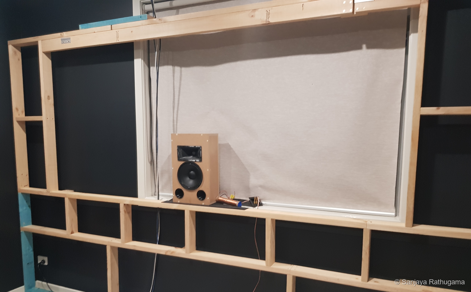
Start with the space behind the baffle
The combination was an SB Audience BIANCO-8MW125 midwoofer and a BIANCO-44CD-K compression driver. They gave me the two sections I wanted to learn to integrate: a direct-radiating woofer and a horn-loaded high-frequency driver.
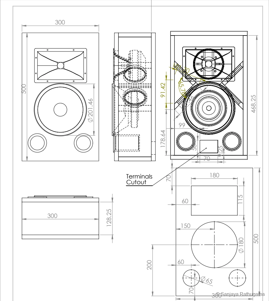
The cabinet design is approximately 500 mm high, 300 mm wide and 160 mm deep. Keeping it shallow made it a relevant experiment for the eventual front wall, where enclosure depth would compete with the space available in the room.
The depth was also a useful discipline. The horn was only one part of the assembly behind the baffle. Its compression driver extended farther back, while the woofer magnet, port ducts and supports needed their own clearances. A front view could make the layout look generous while the side view told a rather different story.
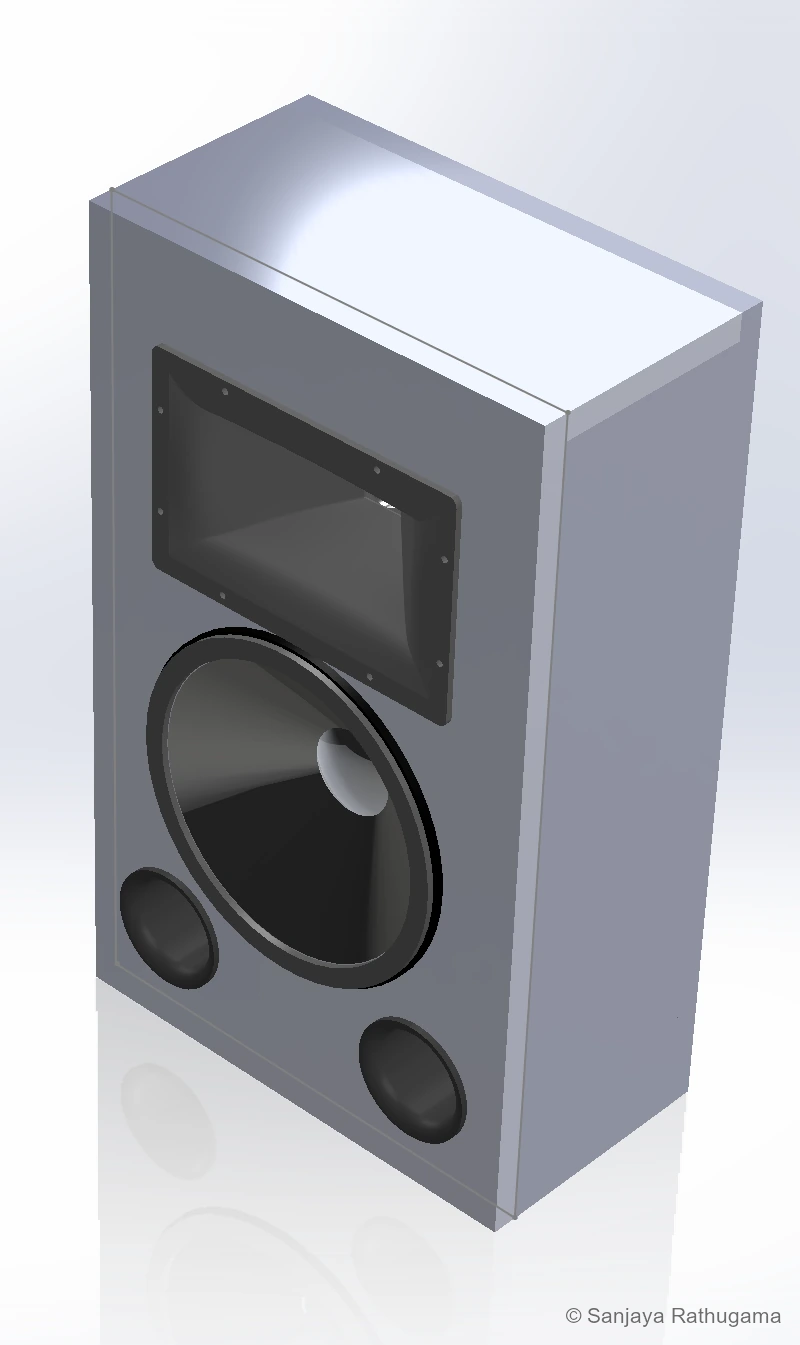
Designing those parts together was useful. I could work on the horn flange and driver attachment while checking where the rear of the driver would sit. I could place the ports without forgetting the space their inner ends needed. Bracing had to support the panels while leaving a shared air space through the enclosure.
The openings in the internal supports served that purpose. They left paths for air and wiring while connecting the panels and reducing unsupported spans. The structure still had to do its job without turning a small enclosure into several accidentally separated cavities.
The volume that the air actually gets
The outside dimensions enclose about 24 litres as a rectangular envelope. That is very different from the volume available to the acoustic system.
The internal dimensions in the CAD are approximately 468 × 268 × 128.25 mm. Multiplying those gives about 16.1 litres before subtracting the space occupied by the drivers, horn, braces and ports. The useful net air volume is lower again.
That distinction connected the CAD work to the enclosure simulation. WinISD's net-volume entry needed to describe the air space, rather than the outside of the cabinet. In a shallow box, the hardware can take a noticeable share of what initially looks like available volume.
It was an early reminder that the mechanical and acoustic designs could not be finished independently. Recovering a little space for a port or moving a support could affect both the available volume and the way the cabinet went together.
What is happening inside the compression driver?
A compression driver starts with familiar ingredients: a magnet, voice coil and diaphragm. Current from the amplifier moves the coil in the magnetic field, and the attached diaphragm moves the air in front of it.
The unfamiliar part was how that motion reached the horn. A small chamber and phase plug guide sound from the diaphragm toward the smaller exit. The phase plug's channels manage the paths from different parts of the diaphragm and influence resonances within the cavity. It belongs to the purchased compression driver; I was designing the horn attached to its outlet.
Dodd and Oclee-Brown's phase-plug research (2007) explains why channel geometry and cavity behaviour matter alongside path length. There is already a carefully designed acoustic system inside the driver before an external horn is attached.
For the BIANCO-44CD-K, the exit is 25.4 mm, or one inch, while the voice coil is about 44 mm in diameter. The horn connection follows the exit size. The voice-coil diameter describes a different part of the driver, and the ratio of those two diameters does not establish the driver's acoustic compression ratio.
The horn then expands from its throat, the small entrance, to the mouth at the front. It changes the acoustic load seen by the driver and influences how the sound spreads into the room. I needed to think about both effects. A high-output driver would be of limited use if its response and radiation pattern did not integrate sensibly with the woofer.
Designing a horn around the experiment
My original horn targeted 90° horizontally and 40° vertically. That gave me a starting geometry to explore, with wider coverage across the seating area and a narrower vertical target.
I tend to call it a short-throat horn, but a more precise description is a shallow horn with a short axial depth. The throat is the entrance itself. The depth describes how far the passage travels before reaching the mouth.
A compact horn helped the assembly fit behind the baffle. Designing it myself also meant I could develop the flare, mounting flange and attachment together, rather than accept a convenient acoustic shape that created an awkward mechanical fit.
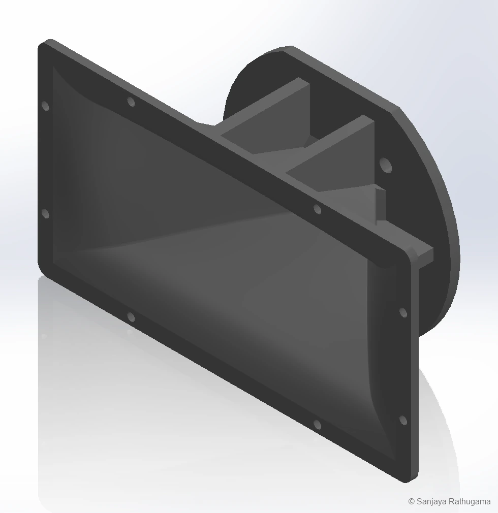
The inlet needed to meet the driver's one-inch exit cleanly. Concentric openings, a sensible transition and a secure seal mattered: a matching bolt pattern alone would not guarantee a good acoustic interface. At the other end, the mouth and flare needed to fit the front panel without making the cabinet deeper than intended.
That was the creative part I enjoyed. The horn was simultaneously an acoustic passage, a load-bearing mounting part and something I had to manufacture. A change to one surface could affect more than the appearance of the opening.
CAD, print, fit, test
I designed and 3D-printed the horn so I could move between the model and a physical part. Printing made a custom shape practical on a hobby project, while allowing the mounting and geometry to evolve together.
The loop was straightforward: design, print, check the fit, test the combination and revise what needed attention. CAD helped catch interference; the printed part exposed assembly details; measurements and listening addressed questions that neither could answer alone.
Printing a shape accurately did not establish its acoustic performance. The 90° × 40° figures were design targets. Actual coverage varies with frequency and depends on mouth dimensions, flare shape, throat transition and the compression driver. Around the crossover, the woofer's output and the spacing between the drivers join the problem too.
The shallow layout was therefore an educated compromise. It helped the packaging and made the part practical to build, while leaving the driver-and-horn response and directivity to be investigated. A deeper horn would change the expansion and loading, but depth alone would not tell me whether the result was wider, narrower or better suited to the room.
Horn profiles and the matching decisions behind the shape
A conical section has straight walls. An exponential horn follows an exponential area law, while a tractrix horn uses a different mathematical contour. Practical horns and waveguides can combine transitions rather than follow one equation throughout. My custom geometry should be understood through its actual shape, rather than assigned a textbook profile because it resembles one in a sketch.
Constant directivity describes an intended radiation behaviour over a useful frequency range. A rectangular mouth or a particular wall angle does not establish it. Likewise, a horn's nominal coverage does not have a hard edge beyond which the sound disappears.
The terms horn and waveguide overlap here. Horn emphasises acoustic loading; waveguide emphasises control of the radiation pattern. The useful question was what this particular driver and passage did together.
| Interface or design choice | Why it mattered |
|---|---|
| Exit and throat diameter | Matching the 25.4 mm entrance helps avoid an abrupt step at the driver interface. |
| Attachment and seal | The flange and bolts need to keep the parts secure, aligned and sealed. |
| Throat transition | The entrance shape has to work with the driver's exit geometry, beyond simply sharing its diameter. |
| Operating range | Driver recommendations, horn loading and the actual high-pass response all matter near crossover. |
| Response and level | The horn-loaded driver's response and sensitivity still need integrating with the woofer. |
Use WinISD to expose the compromises
The enclosure studies made the small cabinet's limitations more concrete. I could change a tuning frequency in seconds, but the new alignment still needed a real air volume, port arrangement and input condition behind it.
One compact BIANCO-8MW125 study used 12.31 litres net, tuned to 90 Hz, with two 55 mm ports. Each port was approximately 102 mm long in that model. This was a compact midwoofer alignment, with the bass extension traded against the small enclosure and intended operating range.
I also explored an alternative 8-inch driver and a larger, lower-tuned version using the BIANCO-8MW125.
| Saved study | Driver | Net-volume target | Tuning | Port arrangement |
|---|---|---|---|---|
| Compact option | BIANCO-8MW125 | 12.31 litres | 90 Hz | Two 55 mm ports, approximately 102 mm long each |
| Alternative driver | BIANCO-8MWN150 | 11 litres | 77 Hz | Two 65 mm ports, approximately 257 mm long each |
| Larger-volume option | BIANCO-8MW125 | 25 litres | 67 Hz | Two 70 mm ports, approximately 154 mm long each |
These were alternatives explored during development. The photographed shallow cabinet did not somehow acquire 25 litres of net volume; that study called for a larger enclosure. Keeping the studies distinct makes the actual design decision much more useful to understand.
Ports take up space as well as move air
The compact model's two 55 mm ducts have a combined opening area of about 47.5 cm². That is the same area as one circular opening approximately 78 mm in diameter. Splitting the area into two ports offered a way to arrange the openings on the small baffle.
The number of ports alone does not determine air speed. For a given total volume flow, the combined cross-sectional area is what sets the average speed through the ducts. Increasing that area can reduce air speed, but maintaining the same tuning generally calls for greater effective port length. Salvatti, Devantier and Button's port study (2002) examines how port geometry affects turbulence and compression.
That made the side view important again. The cabinet had about 128 mm of internal depth before considering obstructions. A model calling for 257 mm straight ducts could not simply be transferred into it. Even a shorter duct needed room around its inner end, and its effective acoustic length depended on the end conditions.
The useful compromise was to consider the alignment and packaging together. Lower tuning was attractive on a graph, but I also had to ask what it demanded from the box, ports and woofer. The prototype was helping me learn how those decisions interacted.
Keep the input conditions with the prediction
The compact study used approximately 125 W input and included a second-order high-pass around 100 Hz. The alternative-driver study used approximately 150 W with a high-pass around 60 Hz. The larger 25-litre study used approximately 100 W without that filter.
Those are different operating conditions. Their cone-excursion or port-velocity predictions cannot be treated as a controlled comparison between enclosure sizes alone. Filtering changes the demand at low frequencies, just as changing the input level does.
I wanted to understand what the model was telling me before choosing the most attractive-looking curve. A small box could be a useful learning platform without being the final answer to the front stage's bass extension or output requirements.
Let the physical speaker answer back
By June 2024, I had driver measurements to bring into the design. On 6 June I measured the compression-driver combination and woofer separately. On 8 June I kept another woofer reading with the back-panel hole closed.
The initial design and testing were done in my office, with a 2.4 m ceiling. These development readings belong to that stage of the work, rather than the completed theatre installation. The theatre's 2.72 m ceiling and later arrangement describe a different acoustic environment.
The REW exports identify a Scarlett 2i2 interface and repeated logarithmic sweeps. They gave me the response of the physical experiment in its measurement conditions: driver, horn or enclosure, placement and room all contributing to what the microphone received.
A note as simple as “back-panel hole closed” became useful once several configurations existed. It connected a curve to a physical change. It did not, by itself, tell me that the whole enclosure was now a completed sealed-box design, or that every other measurement condition matched the earlier session.
The room also made interpretation part of the work. A peak or dip in an indoor response could involve reflections and placement as well as the speaker. Before changing the crossover to correct something, I needed to consider what the measurement actually represented. Saunisto's REW measurement guide (2023) describes the measurement setup, timing and driver data needed for crossover simulation.
The value was in the loop: observe a response, connect it to the setup, form a useful question and decide what to try next. Smoothing made the plot more readable; it did not answer those questions for me.
Build the crossover around the real combination
The crossover developed alongside the cabinet and horn. I began with reference driver data, then brought the measured June woofer and compression-driver responses into VituixCAD.
That was a significant change in the design process. Manufacturer data helped me choose a starting point. My measurements began to describe the combination I was actually making, with its own baffle and horn.
An electrical filter works with the driver's existing behaviour. The driver already has a frequency response, impedance and phase relationship before a capacitor or inductor is connected. A nominal 8-ohm label is useful information, but it does not describe the load at every frequency. Saunisto's 2023 guide explains how to prepare those response and impedance measurements, including their timing reference, before using them in a crossover model.
Level matching was part of the design
The compression driver also needed attenuation to integrate with the woofer. High sensitivity was useful, but leaving the high-frequency section louder would not make the complete speaker more capable. The two sections needed a sensible tonal balance and a handover that worked together.
In the measured-response version, the woofer path uses a series inductor, shunt capacitor and a further series inductor. The high-frequency path includes filtering, resistive attenuation and correction branches. These choices gave me more control over the response than a basic two-component crossover calculation could provide.
| Part of the crossover work | What I was trying to resolve |
|---|---|
| Woofer low-pass | Reduce its contribution as it approached the handover to the horn. |
| Compression-driver high-pass | Shape the lower end of its operating band while considering the driver's recommended range and horn loading. |
| Resistive attenuation | Bring the more sensitive high-frequency section into balance with the woofer. |
| Response correction | Address features in the driver-and-horn response rather than assume either section was flat. |
| Acoustic integration | Consider the summed output, relative phase and driver spacing together. |
The crossover point involved a compromise too. Going lower could ask more of the compression driver and the compact horn. Going higher could leave more of the woofer's upper-frequency behaviour and narrowing radiation pattern in the handover. The useful region had to suit both drivers, rather than whichever one looked easiest to filter.
The June exports do not contain a common timing reference, so they do not establish a verified acoustic crossover alignment or a complete dispersion result. They do document the move from reference curves to measured-response development. The later LCR's digital crossover auditions and final passive-board work belong to that project's next stage, rather than being results from this prototype.
What the smaller speaker changed about the next one
The prototype gave me a custom horn I could manufacture, a shallow cabinet I could package and a two-way speaker I could measure. More usefully, it changed the questions I was asking. Driver choice, enclosure volume, throat geometry and crossover development were becoming parts of one system.
It also clarified what I wanted to increase for the final front stage: displacement capability and output margin for demanding home-theatre playback. Cone area and available linear excursion together determine how much air a woofer can displace. The 8-inch midwoofer gave me a manageable experiment, but I wanted more margin than that combination offered for the larger system I had in mind.
A larger woofer brought its own costs. It needed a wider baffle and more air volume, while the upper-frequency response and directivity still had to integrate with a horn. Moving to a 12-inch unit would not make the crossover problem disappear.
Depth remained the awkward dimension. The next enclosure therefore grew taller and wider rather than simply becoming a much deeper box. The horn's vertical target also widened from 40° to 50° as the larger design developed.
That is what made this prototype worthwhile. I could take an ambitious idea, make the unfamiliar part practical and let the experience improve the next design. The smaller speaker had done its job before I started building the three larger ones.
The continuation is Speakers for a shallow home theatre front wall.
Further reading
Background references published before the 2024 prototype experiments. These explain the engineering principles; my design studies and June measurements establish the history of this particular build.
- SB Audience, BIANCO-8MW125 datasheet, revision 4, 28 April 2023; BIANCO-44CD-K datasheet, revision 5, 10 February 2022: manufacturer data for the prototype combination. The BIANCO-8MWN150 alternative is documented in its revision 4 datasheet dated 28 April 2023.
- Mark Dodd and Jack Oclee-Brown, A New Methodology for the Acoustic Design of Compression Driver Phase-Plugs with Concentric Annular Channels, AES paper 7258, October 2007: phase-plug channels and cavity behaviour.
- Alex Salvatti, Allan Devantier and Douglas J. Button, Maximizing Performance from Loudspeaker Ports, Journal of the Audio Engineering Society, volume 50, January/February 2002: port geometry and flow behaviour.
- Kimmo Saunisto, Measurements with Room EQ Wizard (REW) for crossover simulation with VituixCAD 2, 21 January 2023: preparation of response, timing and impedance data for crossover modelling. The author's page lists this dated guide separately from later software updates.
This is a retrospective account of the 2024 prototype. The later 12-inch speaker's measurements and calibration are documented in its own article.