Before this bench, my garage workspace usually started with unfolding a plastic table.
The lightweight folding tables were useful for putting things down, but they were the sort of tables intended for camping and occasional use. Their height and construction did not suit the work I wanted to do. Whenever a project needed a firm working surface, I was asking a portable table to do a workbench's job.
The height was the part I felt most. The tables sat too low for me, so I spent much of the time leaning over the work. Even a short session could leave me with an aching back. There was no useful storage underneath either. I could put tools on the tabletop, but then they occupied the very space I needed for the job.
The garage clutter was another reason to build it. I had tools scattered around, without a proper place to put them between jobs. The folding tables gave me somewhere to work, but did little to help me organise everything. I wanted to bring the tools together in one place, keep the work surface clearer and spend less time looking for what I needed.
I wanted a sturdy bench at a more comfortable working height, with room underneath for storage. It also needed to move. In a garage, the best position for working is not always the best position for leaving a large bench between projects. A substantial timber frame on levelling castors offered a way to bring the work surface where I needed it, then settle it onto its feet.
The bench came first. The drawers came almost two years later.
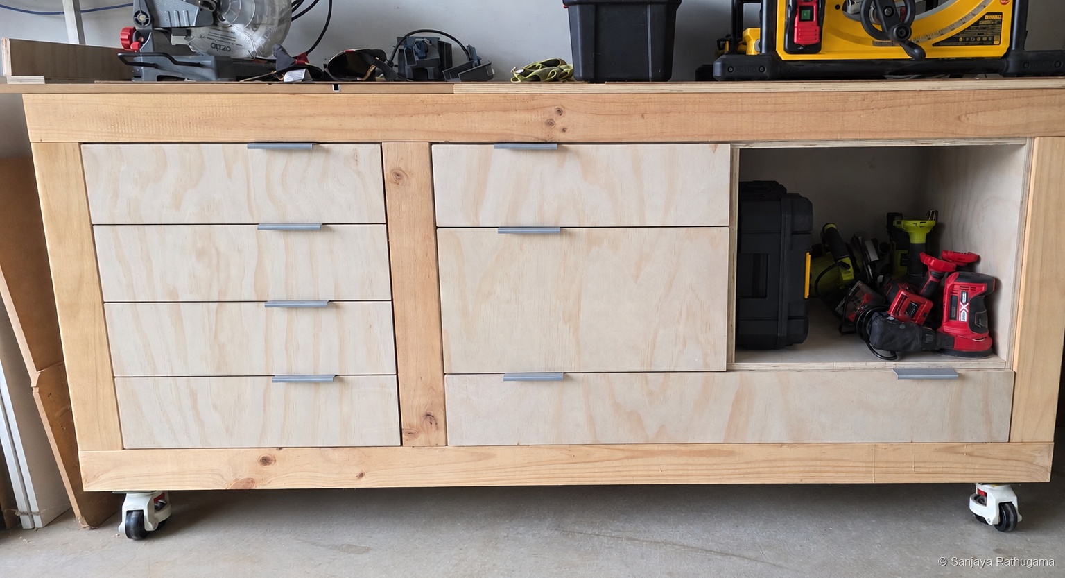
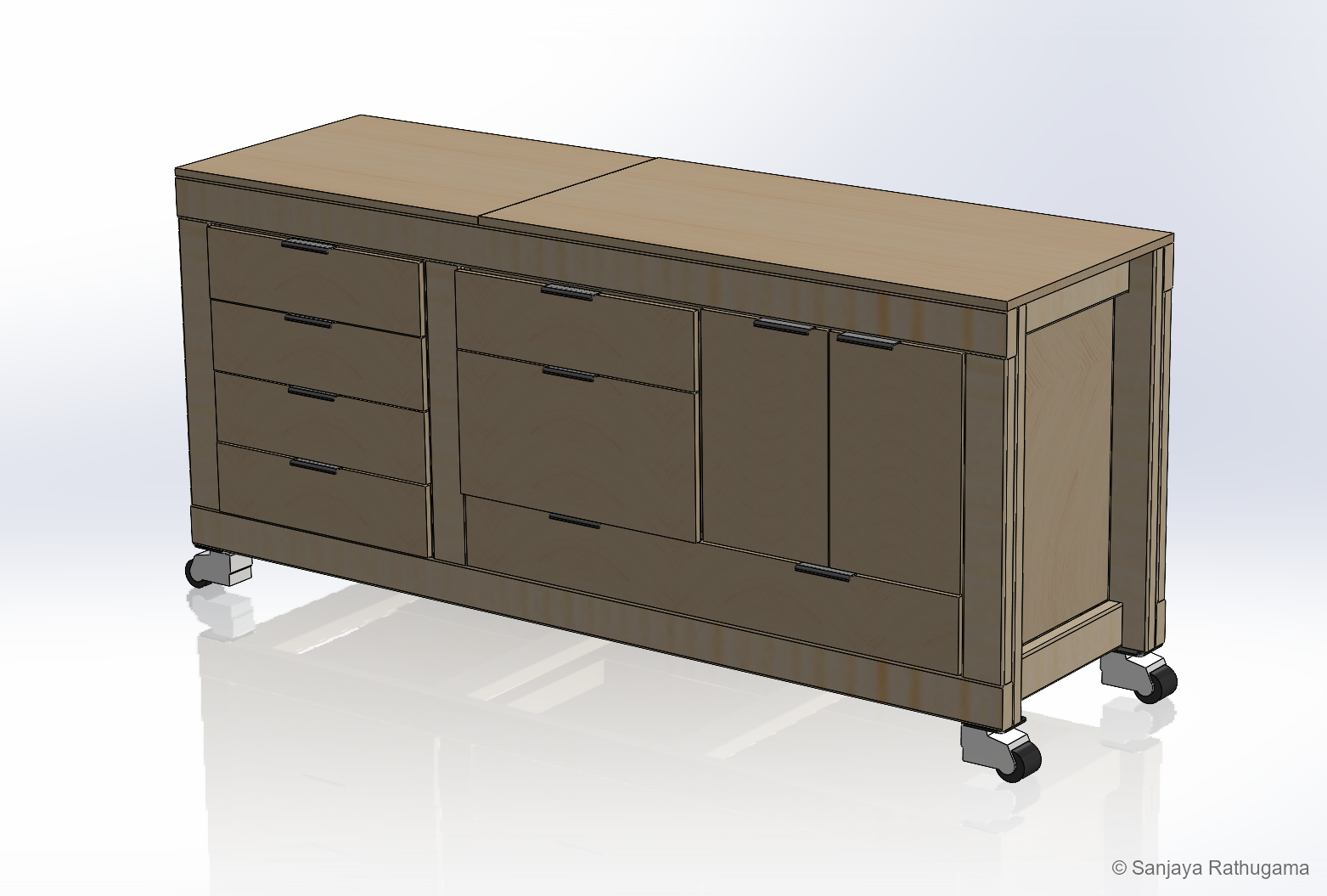
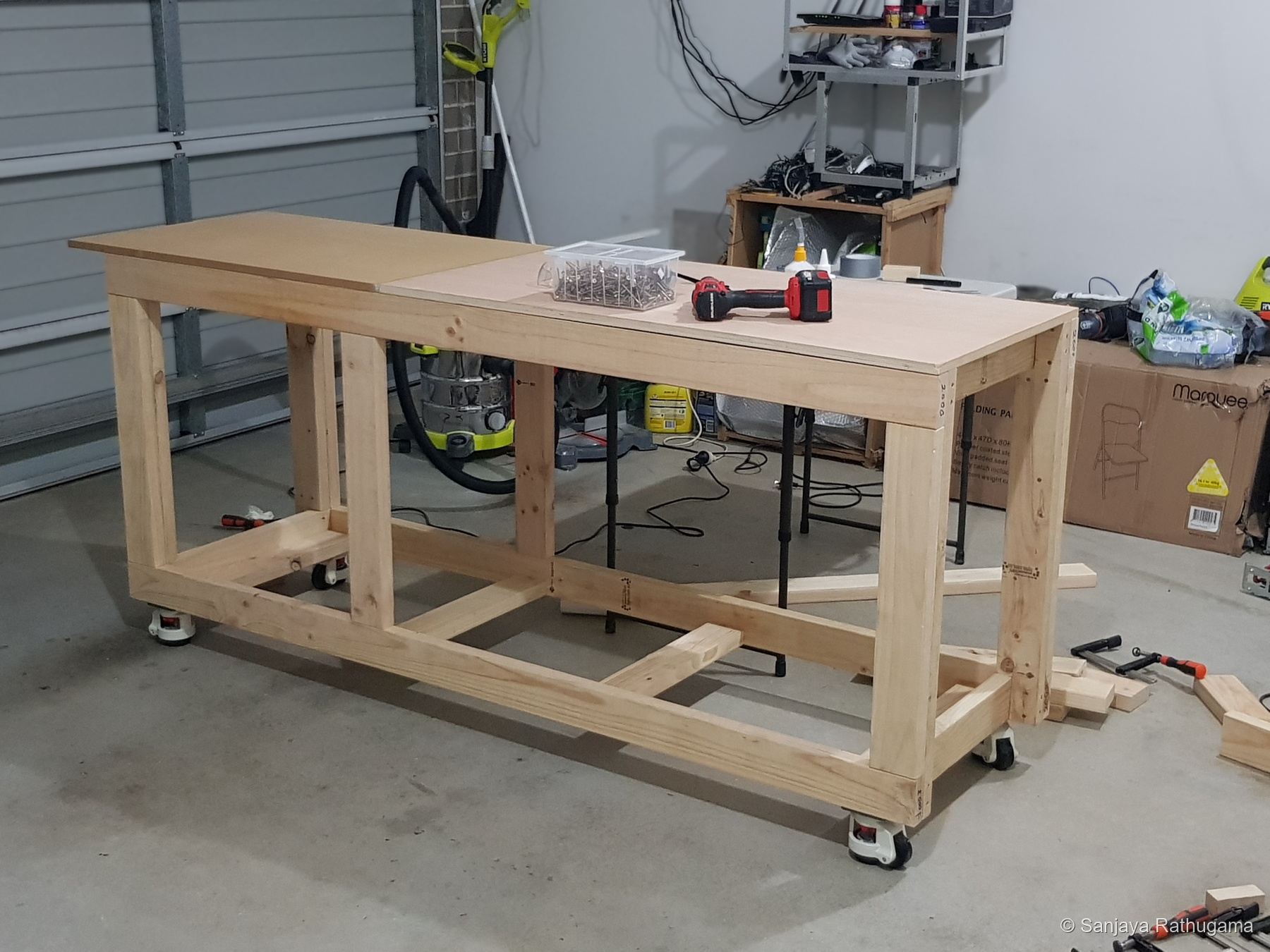
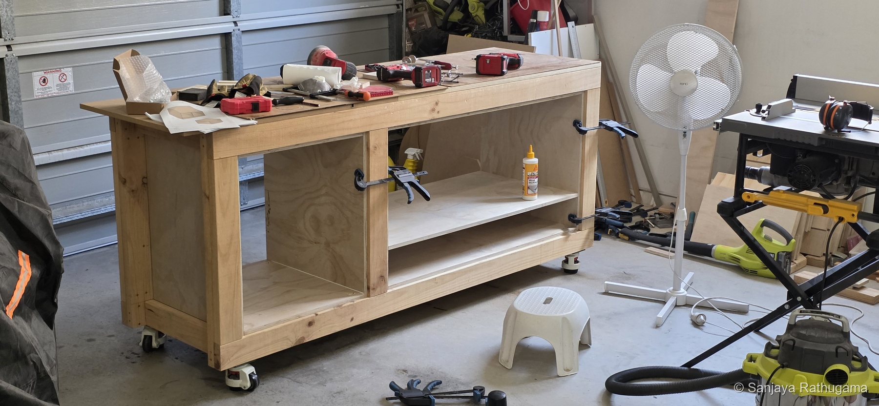
In April 2024 I built an open timber workbench on castors. By early 2026, I was developing the space underneath into fitted storage: four drawers on the left, two in the centre and a long drawer below the centre and right-hand bays. The cupboard doors are still to come.
Storage was part of the reason for building it from the beginning, but I did not have to finish the cabinetry before I could start using the bench. The open frame solved the immediate need for a proper working surface. When I came back to the storage, I had a frame to work within, rather than a blank sheet of paper. Every partition, runner and drawer had to earn its place in the space that was left.
April 2024 | The original bench
I designed the bench in CAD before building the timber frame. The drawing sets out an 1800 mm length and 600 mm depth, with intermediate supports dividing the space underneath.
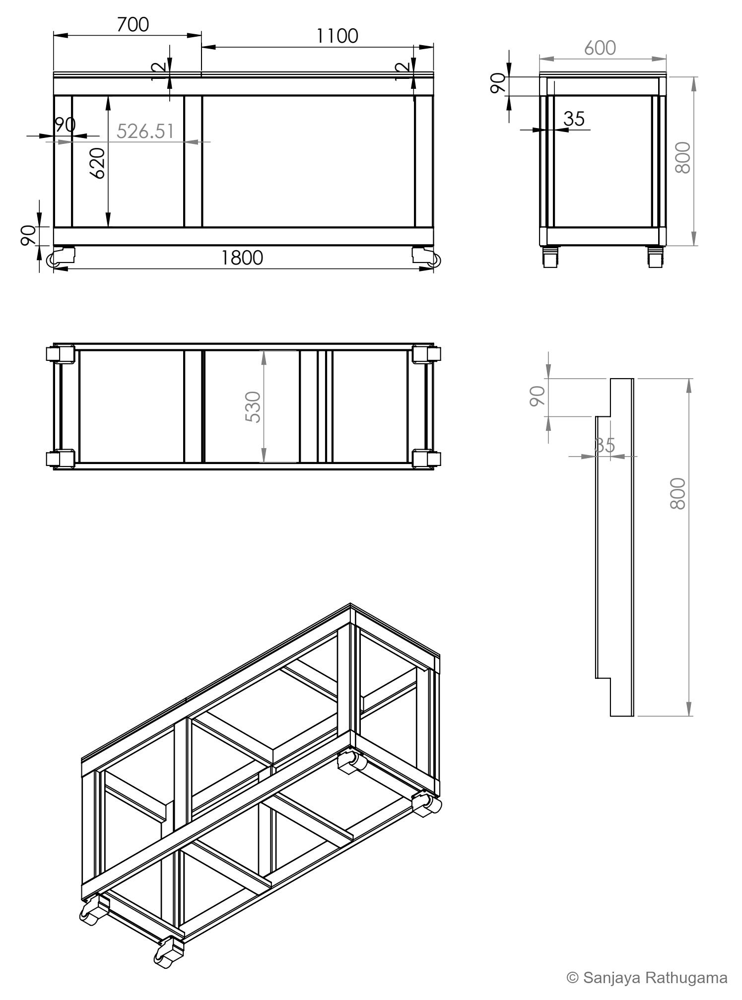
The frame uses 90 × 35 mm pine. Long rails connect the legs at the top and near the floor, while shorter members connect the front and back. This leaves substantial open space underneath the work surface.
The 18 mm plywood worktop consists of two panels, supported by the timber framework underneath. I fixed the panels to the frame using L-brackets and screws. The rails and intermediate supports carry the top across the bench, while the brackets hold it in place.
More than an assembly surface
The bench also took on another job. I used the left-hand section, as viewed from the front, as an improvised saw table, with a Ryobi circular saw mounted beneath the top. It was an inexpensive saw, costing around A$50, and I also made an MDF box to cover the blade.
I built a tray to use with the saw and fitted an aluminium U-channel as its guide track. The tray's rail runs in the channel, guiding the tray along a straight path to help make straight, accurate cuts. I cut a groove into the saw-side panel with a router to recess the channel. Its open end is visible at the front edge, just below the tray.
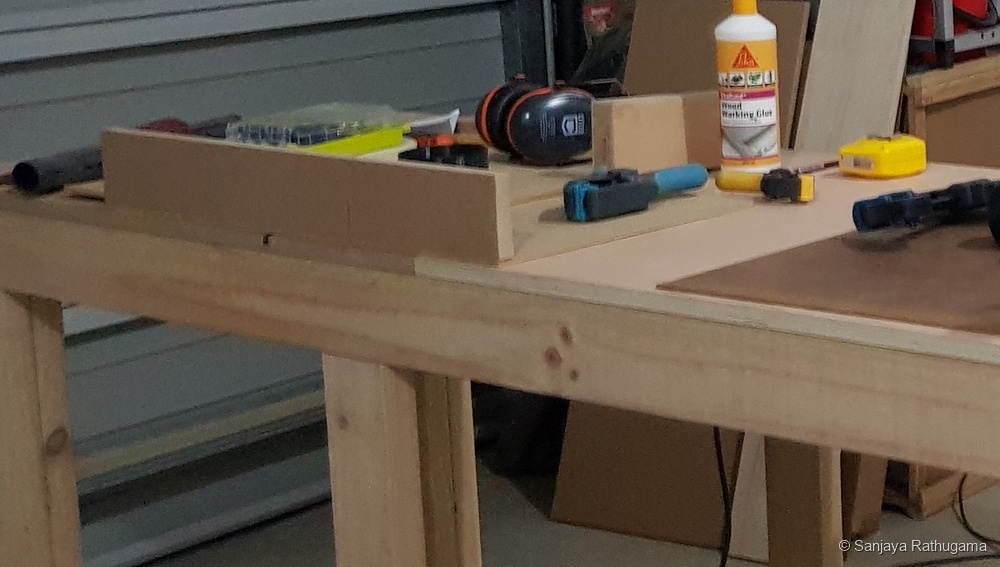
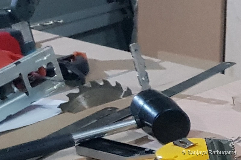
The bench was already supporting other projects well before the storage fit-out. It is easy to look at the finished cabinet and forget that, for nearly two years, this was already a working part of the garage.
A bench that can move, then settle into place
I fitted a set of four GD-80F swivel levelling castors, sourced from Amazon. Each unit combines a wheel with an adjustable support pad beneath a plate mounting. The wheels swivel through 360 degrees for manoeuvring the bench; lowering the pads lets it stand on the feet for use. These are the castors used in the build.
That gives the bench two useful modes: mobile when it needs to change position, and supported on adjustable feet when it is time to work. The individual adjustments also allow the bench to be levelled and its feet brought into contact with the floor. The same principle is described in this levelling-castor overview.
The castors also make storage part of the moving object. Once the drawers are full, their weight travels with the bench. The lower timber rails remain part of that supporting frame; the storage fit-out sits within it.
The drawers were an addition to an existing bench, so their layout had to work around the legs, rails and available openings. A cabinet that looked tidy on its own would not be much use if it fouled a leg or left no room for its runners.
February 2026 | Building inside the frame
The storage fit-out introduces plywood panels within the timber structure. Vertical partitions define the drawer and cupboard spaces, with a long lower compartment spanning the centre and right-hand sections.
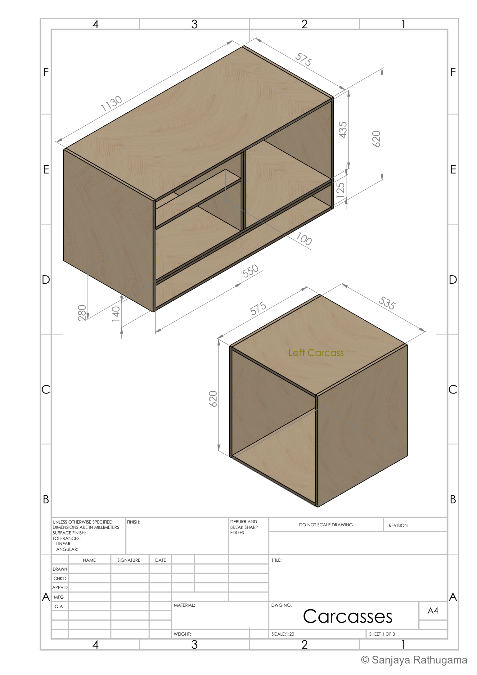
Choosing the panel thicknesses
For the storage fit-out I used CD-grade non-structural plywood from Alpha Timber, supplied in 2400 × 1200 mm sheets. The carcass panels, drawer fronts and drawer-box walls, including the sides, use 15 mm plywood, while the drawer bottoms use 7 mm plywood. Those thicknesses do different jobs. The thicker panels form the boxes, partitions and screw-fixing surfaces. The thinner bottoms close the drawers without using the same thickness everywhere. The supplier's product specification lists the CD non-structural grade and available thicknesses.
CD describes the two surface grades: a C-grade face and a D-grade back. It is a practical utility finish, with visible grain and the possibility of repaired knots and other veneer features. That suits the character of the workshop storage, where the plywood remains visible. The face grade is separate from a structural strength rating; this product is sold as non-structural plywood. More about C-face/D-back plywood.
Plywood is made from bonded layers of veneer, with the grain direction alternating between layers. That cross-laminated construction helps limit movement across a panel compared with a wide board of solid timber. It still responds to moisture, and a thinner panel can still bend under load. The material choice does not remove the need to think about support, especially under the wide lower drawer. APA explains the construction and dimensional stability of plywood.
| Part of the build | Plywood thickness | Role |
|---|---|---|
| Two-panel worktop | 18 mm | Work surface supported by the timber frame and fixed with L-brackets and screws |
| Storage carcasses, drawer fronts and drawer-box walls | 15 mm CD non-structural plywood | Cabinet panels, drawer fronts and sides, and fixing surfaces |
| Drawer bottoms | 7 mm CD non-structural plywood | Bottom panels within the drawer construction |
Turning the design into a cutting plan
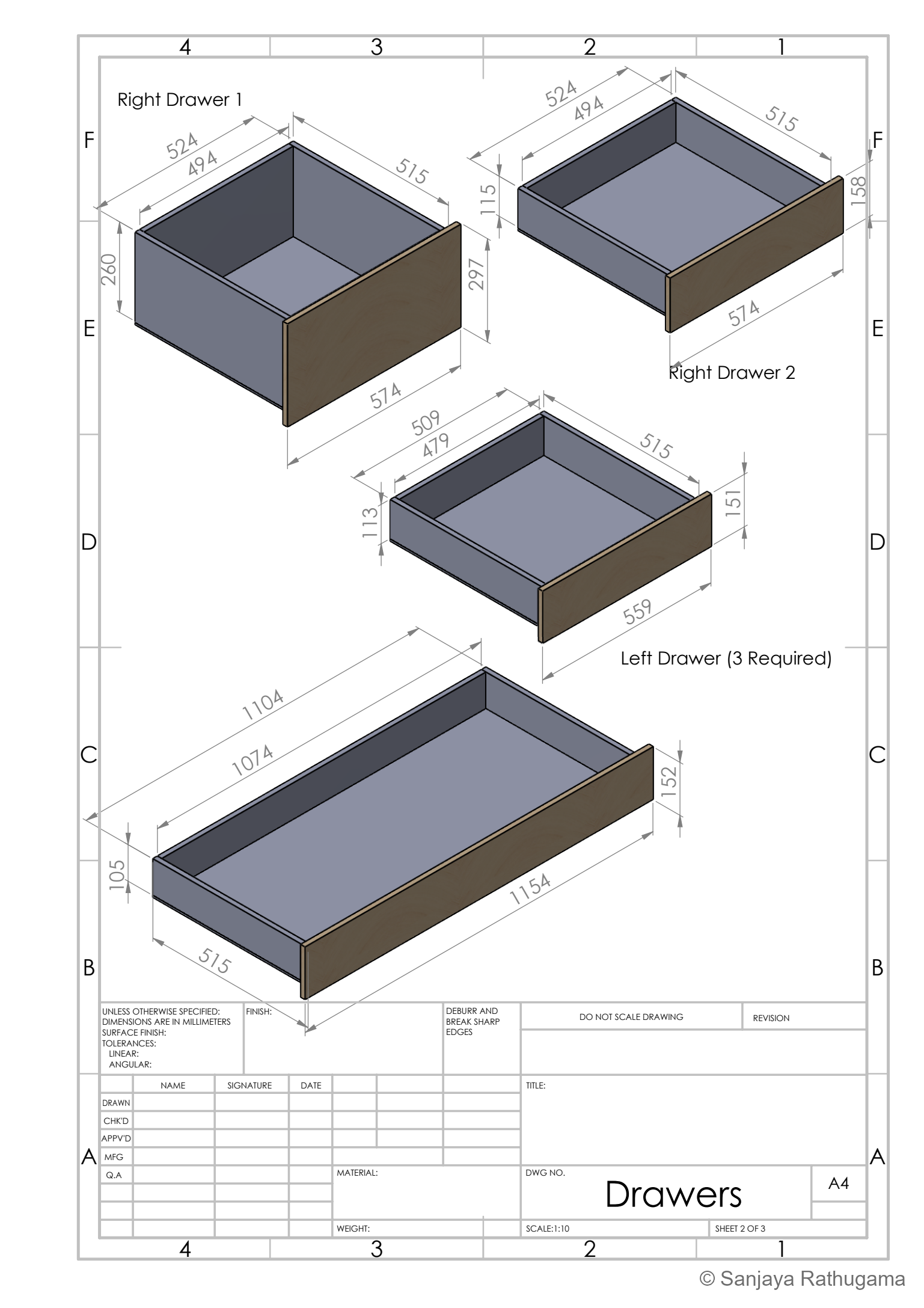
There are quite a few pieces hidden behind a simple front view. The 15 mm cutting plan lays out 51 component panels across six 1200 × 1200 mm working panels. Those are half-sheet sizes within the layout, rather than six full supplier sheets. The separate 7 mm plan arranges the seven drawer bottoms on one 2400 × 1200 mm sheet.
Both plans allow a 3 mm saw kerf. That is the material the blade removes, and it has to exist between adjacent parts in the layout. Two pieces that fit neatly next to each other in CAD will not both come off the saw at the right size if the cut itself has been forgotten.
The layouts gave me a way to work through the panel sizes before assembly. They also separated the repetitive parts from the exceptions: the smaller drawer bottoms could be grouped together, while the long bottom panel needed its own much larger space on the sheet.
This is where a simple-looking cabinet becomes a problem of accumulated dimensions. Panel thickness takes space from the opening. Drawer runners need clearance on both sides. The drawer box must fit between those runners, and its front still needs to sit neatly within the visible frame.
The useful relationship is straightforward: drawer-box width = clear carcass opening − the clearance required by both runners. The clear opening is the space between the finished inside faces, after accounting for the panels. The runner clearance comes from the actual hardware. Confusing either of those with the outside cabinet width would carry the mistake through every drawer in the stack.
Those are different dimensions with different jobs. A drawer front can cover an opening beautifully while the box behind it still needs adjustment. Building and fitting the boxes before adding their separate fronts keeps those two tasks distinct.
March 2026 | Fitting the drawers
The drawers came together progressively. Before fitting the runners, fronts and handles, I had seven separate boxes to assemble and check inside the carcasses.
Keeping the joinery practical
I used pocket-hole joints in the plywood drawer boxes. The front and back panels meet the sides in butt joints, secured by screws driven through angled, recessed pockets. The pockets are visible in the assembly photograph, before the separate fronts cover the outside faces of the drawer boxes.
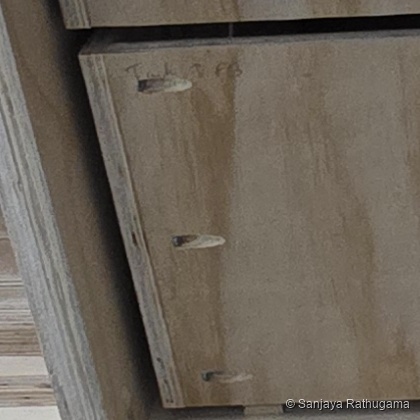
It is a practical method for this sort of construction. The panels can be cut to straightforward rectangular sizes, and the screws pull the mating pieces together. The result still depends on accurate cuts and a square assembly. Pocket screws hold the joint; they do not turn an out-of-square box into a square one.
The drilling setup also needs to suit the actual panel thickness. Jig position, drill-stop depth and screw length work together to put the screw into the adjoining panel without breaking through its outside face. A setting intended for thicker stock is not automatically suitable for 15 mm plywood. Kreg's guidance covers material thickness and pocket-hole setup.
Clamping matters because an angled screw can pull one panel across the other as it tightens. Holding the faces flush and keeping the corner square gives the screw a properly positioned joint to secure. This is one of those small workshop details that can become a much larger problem when a drawer reaches its runners.
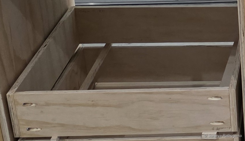
With the drawer boxes fully assembled, I temporarily placed them inside the carcasses to check their fit and overall arrangement: four smaller drawers on the left, a shallow drawer above a deeper drawer in the centre, and the long lower drawer. The separate drawer fascias were not fitted, and the boxes were not yet mounted on runners. The right-hand bay remained available for larger tools.
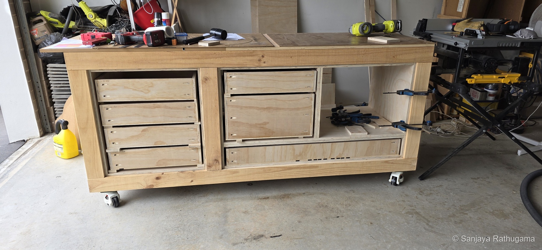
The long drawer uses space below two neighbouring compartments. It gives the lower part of the bench a different storage shape from the individual drawers above, while retaining the original timber surround.
The drawer runners
I sourced the drawer slides from Bunnings and used normal-closing runners for the smaller drawers. The runners sit between the plywood drawer boxes and the carcass, so their thickness has to be included in the drawer-width calculation.
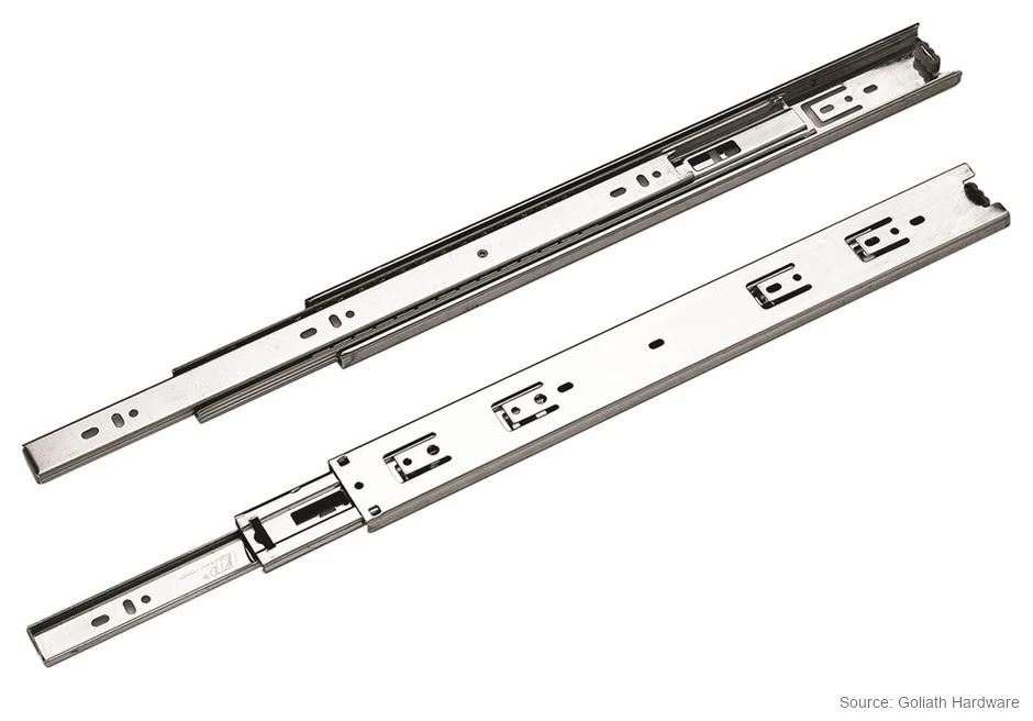
The nested steel sections telescope as the drawer opens, with ball bearings supporting the sliding movement. One member fixes to the cabinet and another travels with the drawer. The fixing holes and elongated slots provide mounting positions along the runner. The slots allow some adjustment during fitting, but the runners still need to be positioned straight and parallel. Goliath describes the standard range and its ball-bearing construction.
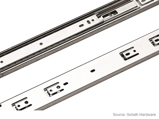
The long drawer uses 550 mm heavy-duty slides. I ended up with that length because the 500 mm version was not available. It is a small example of the hardware influencing the build: the available slide still has to fit within the cabinet depth and work with the drawer, rather than simply being substituted on paper.
For a wide drawer, the two runners also need to remain parallel. Uneven resistance from one side can encourage the box to skew as it is pulled out. Smooth movement depends on the combination of the box geometry, runner spacing and alignment, not just the description on the slide packaging.
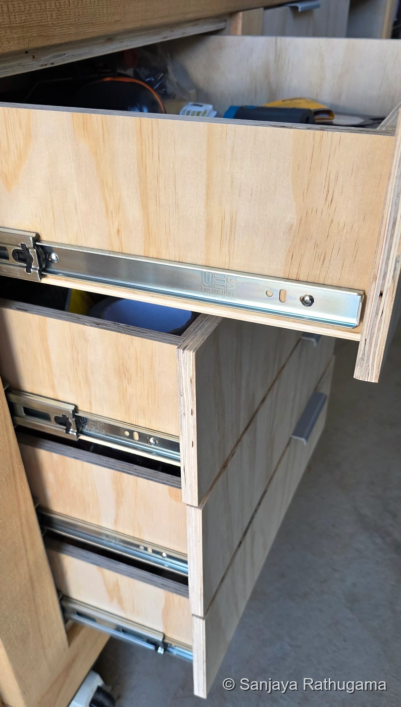
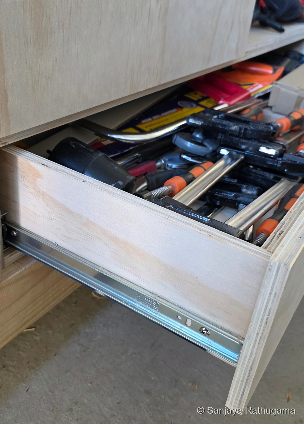
Once all the slides were installed, I could not wait for the finishing jobs. The front panels and cupboard doors were still missing, but the drawers were usable, so the tools went straight in. Apparently storage does not need handles before it starts collecting things.
April 2026 | Fronts, handles and everyday use
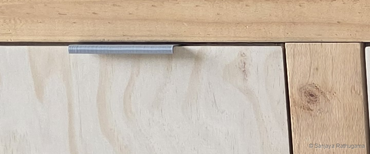
The separate 15 mm plywood fronts bring the storage together visually. My own 3D-printed handles sit near their upper edges, and the original pine frame remains visible around the fitted compartments.
Keeping the fronts separate from the drawer boxes splits the job into two parts. The box and runners establish how the drawer moves. The front establishes the visible gaps and alignment with its neighbours. It also hides the pocket holes on the front of the box, so the useful assembly method does not have to become the finished appearance.
Designing and printing the handles
The handles were another part of the build that I designed myself. I modelled the profile in CAD and 3D printed the handles for the drawers. The design is 120 mm long, with an overall profile measuring 35 mm by 12 mm.
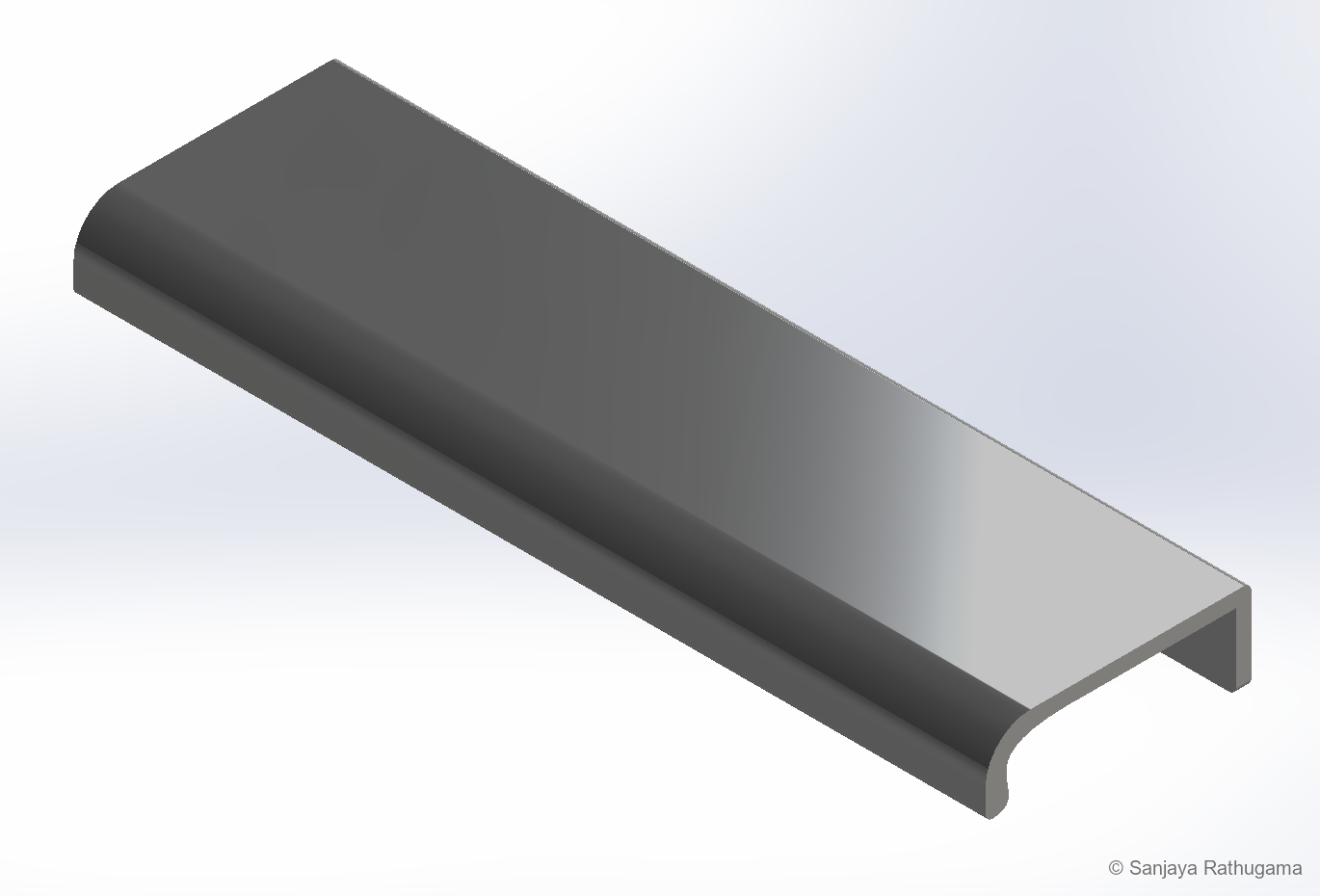
It is a small part, but it changes how the whole front looks and feels. The curved lip gives my fingers an edge to pull against, and repeating the same design across the different drawer sizes gives the storage a consistent appearance. Once the part was modelled, I could print matching copies for the drawers.
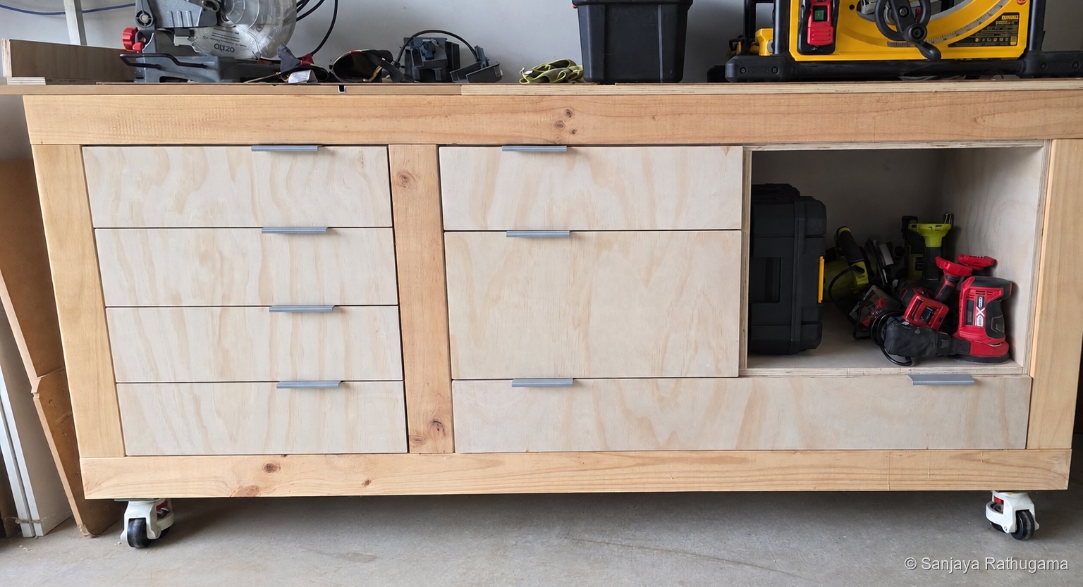
It is now a work surface and a storage unit within the same footprint. Four smaller drawers give one kind of storage, the deeper centre drawer gives another, and the open right-hand bay accommodates larger tools. The wide lower drawer uses the space beneath both central and right-hand compartments.
The two-stage construction is still visible: the timber bench on the outside, with the fitted drawers and cupboard space built into it later. It is a useful reminder that an existing build does not have to be replaced to become more useful. Sometimes the next project is sitting underneath the last one.
There is another job on the list, of course. Those cupboard doors have not installed themselves yet.